
Adafruit Plastic Waste
Adafruit’s inventory management and packaging wastes a lot of single-use plastic.

Adafruit’s inventory management and packaging wastes a lot of single-use plastic.
It was non-trivial to to get CircuitPython building on macOS, largely due to haphazard documentation from Adafruit. This article hopes to improve that.

Flashing the uBlox C209 firmware from macOS


Playing around with some of the current open-source offerings for measuring data (like MQTT and Node-RED) has me wishing all IoT devices supported custom MQTT server configuration.

Cross-compiling Swift code on macOS to target Raspberry Pi.

Realizing an Apollo Guidance Computer in semi-modern discrete logic.

One of my favorite things in the world is The Thrilling Adventure Hour, a stage production in the style of old-time radio, performed live on stage, and recorded as a podcast. This got me thinking about what it was like before television, how people gathered around their radios to listen to radio plays. What if you could listen to The Thrilling Adventure Hour on an old radio?
I bought the T962A desktop reflow oven many months ago, and finally got around to using it. I ended up scorching boards and parts, so I decided to measure the actual temperatures reached on a few of the curves.
We had several successes this weekend, with longer-range flights. We flew the small wing out 2 km, and it successfully returned and landed. A couple days later, we flew out to 3 km. We started to lose telemetry at that range with the rubber ducky antenna, but the plane flew without trouble. Here's a video of a successful flight with autoland:
The wing above is the red one in this photo. The new wing is the black one:
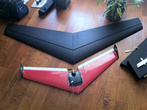
The new wing will use an E-flight Power 32 motor, shown here on the test stand:
I had a flurry of buying activity this weekend, after seeing the new wing. The thing is huge: 2.1 m. I decided to build one, too. The wing it self will take the longest to arrive, some time next week, but I ordered everything else in the mean time, which should arrive before the weekend.
Here’s the list of stuff:
| Item | Source | Price |
|---|---|---|
| Wing | Flying Foam Mothership 2.1 m | $145 |
| Motor | Power 32 Brushless Outrunner Motor, 770 Kv | $74.99 |
| ESC | Castle Creations Phoenix ICE Lite 75 | $110.95 |
| Autopilot | ArduPilot | $250.00 |
| Airspeed | Airspeed Kit | $24.95 |
| Communications | XtreamBee Board | $24.95 |
| XtreamBee USB Adapter | $24.95 | |
| Digi XBP09-DPSIT-156 SMA Connector | $42 | |
| Digi XBP09-DPWIT-156 Wire Antenna | $42 | |
| Lighting | Numerous bright LEDs from SparkFun | $72.50 |
For the last few days I've been troubleshooting a problem with a C++ thread class I created to aid in the static allocation of threads under ChibiOS.
The problem boiled down to the fact that the ChibiOS ARM port (specifically, the ARM7 port, but it's probably true for most ports) isn't properly executing the constructors for statically (globally) allocated class objects. To clean up the other post, I moved the troubleshooting material to this post.
Note: I've discussed this with the author of ChibiOS, and he hopes to resolve the issue in ChibiOS version 2.3.2.
When any object with a vtable pointer is allocated on the stack (i.e. at run time), it works. But when it is allocated as a global variable, the vtable pointer is NULL. Here's the test code and output:
[cpp]
class FooParent
{
public:
FooParent();
virtual void doSomething();
uint32_t mField1;
uint32_t mField2;
};
FooParent::FooParent()
:
mField1(0xBEEFBA55),
mField2(0xDEADFACE)
{
}
void
FooParent::doSomething()
{
}
class
Foo : public FooParent
{
public:
Foo();
virtual void doSomething();
uint32_t mField3;
};
Foo::Foo()
:
mField3(0xFEEDABCD)
{
}
void
Foo::doSomething()
{
}
Foo f;
void
dumpObjects
{
uint32_t* p = reinterpret_cast<uint32_t*> (&f);
sDebug.log("f dump @ 0x%08x: 0x%08x\n", p, *p); p+=1;
sDebug.log("f dump @ 0x%08x: 0x%08x\n", p, *p); p+=1;
sDebug.log("f dump @ 0x%08x: 0x%08x\n", p, *p); p+=1;
sDebug.log("f dump @ 0x%08x: 0x%08x\n", p, *p); p+=1;
Foo g;
p = reinterpret_cast<uint32_t*> (&g);
sDebug.log("g dump @ 0x%08x: 0x%08x\n", p, *p); p+=1;
sDebug.log("g dump @ 0x%08x: 0x%08x\n", p, *p); p+=1;
sDebug.log("g dump @ 0x%08x: 0x%08x\n", p, *p); p+=1;
sDebug.log("g dump @ 0x%08x: 0x%08x\n", p, *p); p+=1;
}
[/cpp]
[cpp]
f dump @ 0x00203090: 0x00000000
f dump @ 0x00203094: 0x00000000
f dump @ 0x00203098: 0x00000000
f dump @ 0x0020309c: 0x00000000
g dump @ 0x00202a60: 0x0010a0a8
g dump @ 0x00202a64: 0xbeefba55
g dump @ 0x00202a68: 0xdeadface
g dump @ 0x00202a6c: 0xfeedabcd
[/cpp]
As you can see, the constructor isn't getting called, (and vtable initialization isn't happening) for the statically-allocated object f, but does get called for object g, allocated on the stack.
This is a GCC issue. It needs to call static ctors (and dtors, theoretically), but it's failing to do so. It could be a mis-configured build of the toolchain, or a bug in the run-time library, or something else along those lines.
It currently fails on ARM (on an AT91SAM7X). The symptom is typical of exceeding the allocated stack space: the processor appears to reset (that is, it re-starts execution from the start of code).
There are two failure modes: in the first, it fails in ThreadEntry(), where the the thread context is cast to a pointer to the BaseThread class, and the virtual entry() method is called, executing the CThread subclass' implementation. If I remove the call to entry() and just implement some code directly in ThreadEntry(), it works fine.
The second failure mode has to do with what I put in the modified ThreadEntry(). Although it executes, subsequent execution later in the program fails (by failure, it is meant that the processor appears to reset).
At this point, I'm not sure what is wrong. Code seems well-enough aligned, when the GCC .map file is examined. The self/this pointer in ThreadEntry() has the correct value. I've tried with very large stacks to ensure I'm not overrunning the stack. I've tried a non-template class hierarchy to be sure virtual method dispatch works correctly (it does).
I'm going to try twiddling some outputs on the MCU (instead of calling the stdlib routines I have been). Without JTAG debugging, it's going to be difficult to figure this out.
On both 8-bit AVR and 32-bit ARM (AT91SAM7X and SAM3S), I've been using ChibiOS. It's a nifty little OS that supports fully-static operation. That is to say, it's possible to allocate all OS structures statically, at compile time, so none need be allocated dynamically at run-time, an operation that can possibly fail. This also allows the exact memory requirements to be known before loading the code onto the target.
I wrote a CThread class (so named to avoid conflict with the OS Thread object) that wraps the allocation of the thread working area and OS thread creation. To do this, CThread is a template class, parameterizing the stack size. Clients subclass CThread and implement the virtual msg_t entry() method.
Note: If you're looking for the description of what goes wrong when the compiler fails to properly initialize static C++ object instances, I moved that material to a new post, Trouble with Static C++ Constructors in ChibiOS/ARM.
In ChibiOS, to create a thread, you allocate the thread working area with a macro provided by the OS, and call chThdCreateStatic():
[cpp]
WORKING_AREA(sMyThreadWA, 512);
msg_t
MyThreadEntry(void* inArg)
{
// …do work
return 0;
}
void
MyProgram::startAThread()
{
Thread* t = chThdCreateStatic(sThreadWA, sizeof (sMyThreadWA), NORMALPRIO, MyThreadEntry, NULL);
}
[/cpp]
The last parameter to chThdCreateStatic() is passed into the thread's entry point. We use it later to pass a reference to the thread class.
As soon as chThdCreateStatic() is called, the thread begins executing. ChibiOS provides numerous synchronization primitives, but we won't get into those here.
CThread ClassThe idea with the CThread wrapper is to provide a class to be subclassed to tidy up the creation of a thread. It would be used like this:
[cpp]
class
MyThread : public CThread<512>
{
protected:
virtual msg_t entry();
};
[/cpp]
And the implementation:
[cpp]
msg_t
MyThread::entry()
{
// …do work
return 0;
}
[/cpp]
Finally, the thread is allocated as a global (as before), and started:
[cpp]
MyThread sMyThread;
void
MyProgram::startAThread()
{
sMyThread.start(NORMALPRIO);
}
[/cpp]
Considerably tidier, isn't it?
Pulling this off requires two classes: A non-template BaseThread class that provides the basic thread functionality, and the CThread template class that derives from it. Note that I do this to try to avoid redundant code generation, which can probably be done using partial specialization or a smart compiler, but I wasn't sure how much luck I would have. The approach does result in a an extra member variable in the base class: the working area size from construction to be used when the thread is started.
BaseThread::entry() should be pure virtual, but I had link errors on AVR with that.
Here's the complete implementation.
CThread.h:
[cpp]
/**
CThread.h
Created by Roderick Mann on 2/3/11.
Copyright 2011 Latency: Zero. All rights reserved.
*/
#ifndef __CThread_h__
#define __CThread_h__
#include "ch.h"
/**
*/
class
BaseThread
{
public:
BaseThread(void* inWorkingArea, size_t inWorkingAreaSize);
void start(tprio_t inPriority = NORMALPRIO);
msg_t sendMessage(msg_t inMsg, void* inContext);
Thread* getSysThread() { return mSysThread; }
protected:
virtual msg_t entry();
private:
static msg_t ThreadEntry(void* inArg);
void* mWorkingArea;
uint32_t mWorkingAreaSize;
Thread* mSysThread;
};
inline
msg_t
BaseThread::ThreadEntry(void* inArg)
{
BaseThread* self = reinterpret_cast<BaseThread*> (inArg);
return self->entry();
}
/**
*/
template<size_t inStackSize>
class
CThread : public BaseThread
{
public:
CThread()
:
BaseThread(mWorkingArea, sizeof(mWorkingArea))
{
}
protected:
virtual stkalign_t* getWorkingArea() { return mWorkingArea; }
private:
WORKING_AREA(mWorkingArea, inStackSize);
};
#endif // __CThread_h__
[/cpp]
And the implementation:
[cpp]
/**
CThread.cpp
Created by Roderick Mann on 2/3/11.
Copyright 2011 Latency: Zero. All rights reserved.
*/
#include "CThread.h"
#include "ch.h"
BaseThread::BaseThread(void* inWorkingArea, size_t inWorkingAreaSize)
:
mWorkingArea(inWorkingArea),
mWorkingAreaSize(inWorkingAreaSize),
mSysThread(NULL)
{
}
msg_t
BaseThread::entry()
{
return 0;
}
void
BaseThread::start(tprio_t inPriority)
{
mSysThread = chThdCreateStatic(mWorkingArea,
mWorkingAreaSize,
inPriority,
ThreadEntry,
this);
}
[/cpp]
What you see above is a little messier than it could be, given a number of issues I ran into while developing it, and concerns about code bloat. But it works reasonably well.
It's amazing how often a problem that seems unsolvable while you're working on it ends up having an easy solution after you put it aside for a while.
Several months ago I wrote about a problem with a Measurement Specialties barometric pressure sensor. I had come to the conclusion that either the sensor was faulty, or I had damaged it during installation on the board. I kept putting off desoldering it, partly because it's a challenging part to solder, and partly because I only had two spares, and they're expensive; I didn't want it to be faulty.

Well, late last night I got the bug to look at it again. The data sheet shows the calculations that need to be made to get a calibrated result, and shows "typical values" for each of the six factory calibration parameters, uncalibrated pressure and temperature measurements, and each step of the process. It never dawned on me that those values might all be part of one measurement and calculation operation.
So I wrote a small app on the Mac that used the same calculation code that was on the sensor board, but put in the example values instead. Sure enough, the result I got did not match, and I started looking into the intermediate results. I noticed one of those was exactly double the example value, and that got me looking at the implementation of the equation. Looking very closely at the data sheet, I started re-writing the equations. Turns out, the code I had found on their site was incorrect, and the code I wrote based solely on the data sheet worked correctly.
For reference, here is C/C++ code that works. mC1 through mC6 are the calibration parameters from the device ROM. mRawTemperature and mRawPressure are the raw sensor readings. mTemperature and mPressure are the final, calibrated result. Temperature is in degrees Celcius * 100, so you have to divide the result by 100 to get the temperature. Pressure is in millibars * 100, so do a similar division to get mb.
[cpp]
{
…
int64_t dT = mRawTemperature - mC5 * 256LLU;
mTemperature = 2000LLU + dT * mC6 / 8388608LLU;
int64_t offset = mC2 * 65536LLU + dT * mC4 / 128LLU;
int64_t sens = mC1 * 32768LLU + dT * mC3 / 256LLU;
mPressure = (mRawPressure * sens / 2097152LLU - offset) / 32768LLU;
…
[/cpp]
This sensor should prove to be very accurate, and will give us the balloon's pressure altitude, as well as the temperature inside the insulated payload box. It's only real drawback is a lower pressure limit of 10 mbar, corresponding to an altitude of about 26 km (~85 kft). We're hoping to go past 30 km (~100 kft). Hopefully the GPS will be a good backup.
The last 24 hours have been an exercise in frustration, sleeplessness, wrong turns, dead ends, and embarrassment. I've been working on a little project that developed a problem, seemingly inexplicably, and I could not find the cause.
This little AVR-based project includes a 16x2 character LCD display. For the last week, it has been working like a champ. I got a lot of fundamentals worked out, and decided to start cleaning up the code. It had gotten to be quite a mess, as I quickly worked through the various building blocks of the overall device, and I needed to make it look more like the final product would.
I would make small changes, compile them and load them onto the device, making sure things worked, or worked the way I wanted them to. Suddenly, the LCD stopped working. I could tell the MCU was doing its job, as the heartbeat LED kept blinking, and I was getting debugging output from the serial console attached. But no LCD.
Since the last change I made was to add a MOSFET so that I could power down the LCD when not in use, I thought perhaps I had damaged the LCD. I removed the new circuitry, and spent some time searching for a similar LCD to try. Found one, popped it in, and it behaved the same way!
Perhaps I had damaged the MCU. Unlikely, because everything else was working perfectly. So I replaced that, flashed it, and tried again. No dice. Now, I was already operating on very little sleep this weekend, and it was after midnight. Had I been firing on all cylinders, I would've abandoned the effort and gone to bed. Or had looked for a software problem first. But I had been on such a roll, and I don't back down easily from a challenge like this.
I fired up the oscilloscope and started probing the connections between the MCU and LCD. They were one of the first things I had checked, making sure everything was still connected. Since I had tried the new MCU with the old LCD, I thought maybe it was damaging the MCU pin drivers. So I checked each one to see if it was changing state.
I found five that weren't! I pored over the code, thinking somewhere I had introduced a change (by accident), that disabled some of the pins. I couldn't find anything. I tried a third MCU. I tried a third LCD. Nothing. Same five pins not working. Then I realized that there must be an internal peripheral on those pins inside the MCU that was overriding the general I/O functionality. Looking at the data sheet, I saw that the JTAG interface lived on those pins, and a vague memory floated up: new MCUs have the JTAG enabled by default.
So, I disabled that, excited that I had figured things out, and tried again.
No luck. Still didn't work. Argghhhhhh!
I gave up. Went to bed (now well past 2 am), got up late the next morning, went to work, came home. Watched an hour of TV, then came in here to figure out the problem.
I decided to revert my source code back to a known-working revision. I was currently on revision 15, and the checkin comments showed the LCD had started working after r7. So, I updated my code to that revision, and tried it. It worked! Praise jeebus!
I tried to see the differences between that code and the latest, but there were too many changes. I updated to the latest code and tried again, just to verify the problem was in the code, and it still worked! WTF? Now, somewhere in here I had made a couple other changes to the code, trying to undo the most recent additions. The latest code had those changes (I had checked them in before reverting), so I was really confused.
But sure enough, it seemed to work. So I put back the code I had just taken out, to try to reproduce the problem. It still worked. WTH? (Ironically, I was now looking for failure, because that would tell me I had figured out the "root cause," as NASA likes to put it.) I could not reproduce the problem.
So, I cleaned up the recent experimentation, checked in the code, and set about to do new work. I wanted to measure the current consumption in various operating modes, so I wired in the ammeter.
Suddenly, the problem reappeared. Argghhhhhh!
I started to think that I wasn't giving the LCD sufficient voltage. The prototype design had a diode from the Vcc to the rest of the circuit, and I thought maybe that little voltage drop was enough to cause problems. That didn't really explain why it had been so reliable up until now, or why it was so unpredictable. I thought maybe the LCD backlight was drawing too much current, and the supply was sagging. Maybe I had accidentally increased its brightness in the code. So I set it to be really dim. No help. I removed the diode. No help.
It finally occurred to me that perhaps I wasn't giving the LCD enough time to get stable power before beginning the initialization sequence. I went looking for the lcdInit() call in the code to add a small delay before it. But I couldn't find it! Some where in last night's cleanup, I had deleted the call to initialize the LCD! The cascade of emotion that washed over me was intense. Relief that I had finally tracked down the problem, anger at the hours wasted, regret for the sleepiness I'd felt all day, all stewing in the embarrassment that I hadn't gone about the troubleshooting more methodically.
I put the call back in, and everything worked great. Phew.
But why did it sometimes work and sometimes not?
It turns out, the LCD currently doesn't get shut down when the system goes to sleep or resets. So, when I ran older code, the LCD got initialized. When I loaded newer code, it remained initialized, and so would work. But when I disconnected power in order to insert the ammeter into the circuit, the LCD reset itself. Because I was pulling power to the circuit deliberately to try to track down the problem, it was resetting itself.
So many time-consuming wrong turns, so many red herrings. In the end, it was a software problem, one I should have caught much earlier, but because I didn't carefully examine all the changes made between revisions, I didn't notice it.
Hopefully a lesson re-learned.
I'm probably just procrastinating a bit before getting into writing firmware for this thing, but I though I'd post a picture of the Balloon Controller with nearly everything populated. I'm still waiting for the barometric pressure sensor and GPS connector to arrive, but everything else is installed.
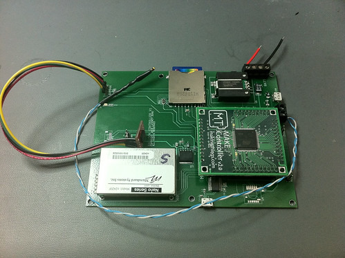
I've verified that everything powers up, but beyond that, I have no idea if anything works. I was able to flash the MC with a blinky LED program, though, so that's a good start.
UPDATE (15:38): Got the DBGU serial port work. Note that this board has two USB ports. One for the MC proper, and one for an FTDI chip attached to the SAM7X's DBGU port. This was easier than writing a Mac OS X virtual serial port driver against the MC's USB port.
UPDATE (18:27): Got the battery voltage being measured, and also got the radio link working!
It's a little cumbersome to flash the MC when you have an external power source, because it needs to power cycle to re-enumerate the USB and set up for download. So I pulled the fuse that USB bus power goes through, which means that I only have to disconnect the main power supply to power cycle it, rather than disconnect that and unplug the USB cable.
Darren and I tried an 18 km range test today with the n920. Amazingly, we had success with just the rubber ducky antennas, and down to 250 mW transmit power on both ends! He was up near this winery, and I was on the fifth floor of Yahoo! building D.
At first we tried the new Yagi, but it didn't seem to work (at all). We were astonished to get a link with just the whip antennas. They didn't even have a proper ground plane, just being stuck out the side of the plastic boxes I had put the gear in (and pointing upward).
Using the ATS123? command to query the receive signal strength, Darren had -88 dBm, I had -105 dBm (measurements varied, but I think that was at 250 mW). I tried sending a file to myself via loopback, < 1 KB in length, which failed the first time and succeeded the second. A 131 KB file failed, and I didn't try it a second time. I could see it dropped stuff from within the file. We'll have to investigate exactly what went on. Are the radios full duplex? How big are their buffers? It seemed to send the entire file before receiving anything, but that could've been an artifact of PortTermX.
Interestingly, the Yagi didn't seem to offer much. It was also nearly impossible to hold while operating the computer. Next time, we need to put it on a stand of some kind.
Hopefully this weekend we'll try a much longer range test, from the winery to Coyote Hills.
Our balloon experiment is using a 920 MHz frequency-hopping radio link (we also have 2.4 GHz radios, but will probably stick to 920 MHz). The balloon will carry a dipole or vertical bazooka tuned for 920 MHz, but it will be rotating and squirrelly. It will also be 30 - 50 km away. So I decided a good Yagi on the ground will help ensure we maintain our fade margin.
I looked at a couple options from L-Com. The best 900 MHz Yagi they had offered 14 dBi in 109 cm, but was $120. The next best offered 13 dBi for $44, so I bought it. I didn't realize until it arrived that it was 145 cm long!
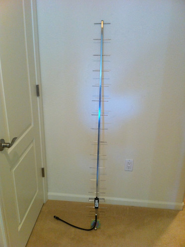
So, this will prove to be unwieldy, at best, especially from a moving car. We might decide to have a fixed ground tracking station, but that approach will need investigation.
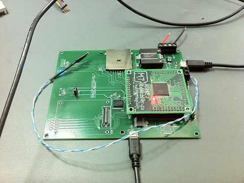
I've been hard at work this week on the Balloon Controller. It's an ARM-based embedded system with a bunch of sensors, intended to be flown as a payload on a high-altitude balloon. I'm very nearly finished with the PCB layout, but I thought I'd post a picture of it anyway:
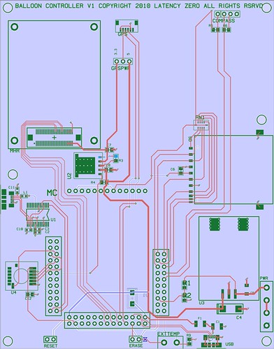
The board features:
This is just a prototype. The next version will feature an Atmel SAM3S MCU instead of the Make Controller, some GPIO, and more refinement. It might even have an image sensor interface and be able to downlink images in real-time. And they'll be available for purchase, although we'll look at alternatives for the communications link, because the n920 radios are fairly expensive.
Stay tuned for updates.
I've seen a lot of reports lately of recent and past amateur balloon launches. People have been launching sounding balloons with payloads containing GPS and cameras, and have been very successful. I've wanted to do this for some time, and coming across all these reports has excited me about the idea again.
Really what I want to do is launch a satellite. So I've decided to expand the scope of the balloon launch in support of a future satellite launch. I've ordered the Microhard radio we'll be using on the satellite to test on the balloon.
We're going to build a payload with GPS, temperature, pressure, still pictures, and possibly video. Lots of work to do in the link budget calculation to see what we can do, and within the 1.8-kg payload FAA limit. We're also building a directional 2.4 GHz antenna to automatically point at the thing (a project I began a couple years ago for UAV use).
This is going to be fun. Check back for updates.
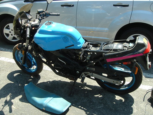
I’ve decided to convert my old motorcycle to electric. This involves ripping out all the gas-related parts, and putting in an electric motor, batteries, and associated control electronics to make it all work. I’ve started a new blog for the project, go check it out:
I came across a page about peak-power tracking in solar PV applications. I decided I wanted to goof around with solar stuff, so I started tinkering. This is what I have so far:

So far there's not much going on. It measures voltage generated by the panel, and current being delivered to the load (a little red LED in this picture; the circuit is powered from a bench supply). I started adding a 5-volt LDO, which I'll use to regulate power to the MCU and LCD when powered from the panel.
If I can get AVaRICE to stop hosing my ATmega324P parts, I'll slow this down to 4 MHz (it's running at 16 MHz here) and power it from 3.3 V. That should work better in actual sun-powered applications.
I got my net4521 a few days ago, and after borrowing a CF card ('cause I stupidly forgot to get one of my own), I had it up and running Pebble Linux (from Tor Amundson) in no time. A few days later the CM9, miniPCI 802.11a/b/g card, arrived.


I've been poking at getting the 802.11 card up-and-running, and met with some success. Right now a kind soul is helping me learn how to use buildroot to build a Linux from the ground up for use on this box. We'll see how that goes, and I'll try to post the steps here.
This note briefly describes how to set up PWM on an ATmega32. In this instance, Timer/Counter 1 (16-bits wide) is used to set up a Fast PWM-mode PWM wave to drive a typical R/C servo. The PWM period is 20 ms (50 Hz), and the pulse width varies from 0.9 ms to 2.1 ms.
With a 16 MHz clock, the full 16-bit count wraps around in about 780 µs. Since we need a PWM period of 20 ms, this is clearly too fast. Prescaling Timer/Counter 1 by dividing the sytem clock by 64 gives us a full-count period of 50 ms. By setting the upper limit of the count using ICR1 to 12500, this results in the desired 20 ms period.
Update: I’ve gotten some math wrong in the preceding paragraph, and I'm not sure what I was thinking. It seems that a full 16-bit count would take 4.096 ms at 16 MHz. Also, the comments in the code regarding prescaling values don’t all agree. Sorry about that. I hope you can still find this useful.
To get the appropriate servo pulse width between 0.9 ms and 2.1 ms, the OCR1A register is loaded with values between 225 and 525.
Please excuse the lack of a schematic; I simply don’t have time to create one right now.
The ATmega32 is set up to run with a 16-MHz crystal oscillator. On the PDIP 40 package, the following pins are connected:
| Pin | Description | Connections & Use |
|---|---|---|
| 6 | PB5/MOSI | ISSP |
| 7 | PB6/MISO | ISSP |
| 8 | PB6/SCK | ISSP |
| 9 | Through 10 kΩ resistor to Vcc, N.O. switch to GND, ISSP | |
| 10 | Vcc | Power, 0.1 µF ceramic cap to GND, ISSP |
| 11 | GND | Ground, ISSP |
| 12 | XTAL1 | To 16 MHz crytsal, 10 pF ceramic cap to GND |
| 13 | XTAL2 | To 16 MHz crytsal, 10 pF ceramic cap to GND |
| 19 | PD5/OC1A | To Servo signal line |
| 30 | AVcc | Power, 0.1 µF ceramic cap to GND, ISSP |
| 31 | GND | Ground, ISSP |
| 40 | PA0/ADC0 | To LED, LED to 470 Ω resistor, resitor to GND |
The fuses are set for a 16 MHz external crystal oscillator.
| Name | Description | Value |
|---|---|---|
| Fuse Lo | Fuse Low Byte | 11101111b, 0xEF |
| Fuse Hi | Fuse High Byte | 10001001b, 0x89 |
The following registers are set, in this order. Although the order isn’t strictly necessary, some subset of it might be (be specific).
| Name | Description | Value |
|---|---|---|
| DDRA | Port A Direction | 00000001b, 0x01 (PA0 output, rest input) |
| DDRA | Port B Direction | 00000000b, 0x00 (all input) |
| DDRD | Port D Direction | 00110000b, 0x30 (PD4, PD5 output, rest input) |
| TCCR1A | Timer/Counter 1 Configuration A | 10100010b, 0xA2 (OC1A & OC1B set at BOTTOM, clear on compare match, WGM=14 [fast PWM, ICR1 is TOP]) |
| TCCR1B | Timer/Counter 1 Configuration B | 00011011b, 0x1B (prescale ClkI/O/64) |
| ICR1 | In Fast PWM mode, becomes TOP | 12500d (20 ms PWM period with ClkI/O/64 prescale) |
#include <inttypes.h>
#include <avr/io.h>
#include <avr/interrupt.h>
#include <avr/signal.h>
#define kPinInitCompleteLED         PA0
#define kDelay                      10000
#define kReverseDelay               300000
#define kLowerLimit                 300                 //  Min 225 == 0.9 ms
#define kUpperLimit                 450                 //  Max 525 == 2.1 ms
int
main()
{
    volatile long       d;
    short               dir = 1;

    //  Set LED output pins…

    DDRA = _BV(kPinInitCompleteLED);
    DDRB = 0;                                           //  Port B inputs

    //  Set up OCR pins (PD4, PD5) as outputs (00110000)…

    DDRD = _BV(PD4) | _BV(PD5);

    //  Set up Timer 1. Timer 1 should reset when
    //  it reaches TOP = ICR1 (WGM13:0 = 1110b). On
    //  compare match clear output, at TOP set (COM1A1:0 = 10b).

    TCCR1A = _BV(COM1A1) | !_BV(COM1A0)                 //  Both PWM outputs set at TOP,
                | _BV(COM1B1) | !_BV(COM1B0)            //    clear on compare match
                | !_BV(FOC1A) | !_BV(FOC1B)             //  PWM mode, can't force output
                | _BV(WGM11) | !_BV(WGM10);             //  Fast PWM, TOP = ICR1

    TCCR1B = !_BV(ICNC1) | !_BV(ICES1)                  //  Disable input capture noise canceler,
                                                        //    edge select to negative.
                | _BV(WGM13) | _BV(WGM12)               //  Fast PWM, TOP = ICR1
                | !_BV(CS12) | _BV(CS11) | _BV(CS10);   //  clk(i/o) / 1024

    //  PWM duty cycle…

    OCR1A = kLowerLimit;
    OCR1B = kLowerLimit;

    //  PWM period…

    ICR1 = 12500;

    //  Show initialization complete…

    PORTA = _BV(kPinInitCompleteLED);

    //  Loop forever steering left-to-right-to-left…

    OCR1A = kLowerLimit;            //    Min value == 0.9 ms
    while (1)
    {
        d = kDelay;
        while (d--);

        OCR1A += dir;

        if (OCR1A < kLowerLimit)
        {
            OCR1A = kLowerLimit;
            dir = 1;
            d = kReverseDelay;
            while (d--);
        }

        if (OCR1A > kUpperLimit)    //    Max value == 2.1 ms
        {
            OCR1A = kUpperLimit;
            dir = -1;
            d = kReverseDelay;
            while (d--);
        }

    }

    return 0;
}
Okay, so I lack focus. Too many projects. School and work, whatever. I’ve finaly gotten most of the parts for the new base constructed. I used EMachineShop to make the motor mount brackets, and found EPPCO, a local Berkeley machine shop, to do the axle block.

|

|
| Assembled base three-view | Assembled base overhead (actually underneath) |

|

|
| Side view | Drive train closeup |

|
|
| Drive train overhead view | |
Wow, it’s been a long time! But in an ongoing effort to avoid studying and homework, I'm mucking about with the Ichibot and associated pages.
Even though I haven't gotten very far with Ichibot, I’ve decided to build a new, better mechanical platform for it. I’ve designed the chassis, and am currently looking for way to get it machined. I’ve also purchased the necessary hardware, pictured below (click the images for a larger version, or the links for a huge version).

|

|
| Full-sized image of separate parts | Full-sized image of partially assembled parts |
Full-sized image of separate parts Full-sized image of partially assembled parts
The new Pittman motors (part GM8724S021-R1) are much better than the old JameCo motors. They are 12 VDC motors with 60.5 : 1 reduction gearheads and 500 CPR encoders. They were $195 each, and I’m a little concerned that I ordered too much gear reduction. Some people on the robotics lists have all suggested I’ll be happy to have the torque, and that the output shaft speed is sufficient. We’ll see.
The new chassis will look something like this. I need to redo the CAD. I’ll post complete drawings and make the files available.


Yesterday I added training wheels to the bot and allowed it to run free in the kitchen. The “training wheel†is a simple furniture caster attached to a 1.5" wide piece of aluminum bent in two places and bolted to the frame. The controller is running a very simple navigation program. It basically goes forward for two seconds, turns right for one, repeat. The timing is too far off to make any kind of recognizable shape, but it was a chance to see the ’bot in action.


There’s also a short high-power burst forward and backward (and forward again) to qualitatively determine what kind of torque characteristics the system exhibits. Interestingly, it’s enough to kick the caster wheel up off the ground, despite having two battery packs strapped to it.
For its first untethered tests, I added two 6-cell, 3000 mAh NiMH battery packs (the kind used in electric R/C race cars and planes) wired in series to give a nominal battery voltage of 14 V. This makes for rather large drop across the controller’s main regulator (and might even be outside the spec; I’ll have to take a look). Perhaps I should tap off of one of the batteries for powering the electronics.
What a crummy day. I spent so much time fiddling with the LCD code that I broke. I had started writing a basic PD speed controller. I was writing a fair amount of info to the LCD during the PD loop interrupt, which was taking quite large portion of the available executiong time, so I tried to tighten up the LCD code (more details in a later post). Well, I broke it. Many, many hours later, and after fixing it and having it all of a sudden stop working multiple times, I got it and the PD code working.
Now, I based this off an old article written by David Anderson. It does something interesting. If you command a speed of zero, and then turn a wheel by hand, it will resist that effort like a spring. If you then release the wheel, it will rotate back to its approximate starting point.
The calculation of the PWM signal is cumulative, even if there is an error of zero, so the PWM is being integrated (I think). I need to brush up on my understanding of PID controllers to figure this one out.
Okay, I’m a dork. I made so many mistakes trying to figure out this serial communications thing, it’s not even funny. But, I’ve got it working now.
Two major things went wrong. First, I failed to realize that the ’32, by default, operates off of its internal 1.0 MHz oscillator. You have to program clock selection bits as a separate step to get it to use an external crystal (which I had connected, but didn’t realize wasn’t being used). Since all of my baud rate calculations were being done assuming a 4.0 MHz clock, they were way off (which explained the bizarre timings I was seeing on the TX pin).
Unfortunately, try as I might, I still can’t seem to get the external crystal to work. I’ve succesfully driven a PIC16F877 at 20 MHz on perf board, so I’m not sure why I can’t get the ATmega32 to run at 8 MHz.
So I punted on trying to get the crystal to work, and configured the MMC to operate at 9600 bps instead of 38.4 kbps (the ATmega32 can’t drive a serial line at 38.4 kbps with less than 8.5% bit-rate error, and that may be too much for the MMC). After much futzing with this speed, I still couldn’t make it work, which brings us to my utter stupidity: the MMC wasn’t fully seated in its socket, and so wasn’t actually getting the signal!
It’s working for now, and so I’m going to spend some time actually writing software. I’ll write code to run the motors at a constant speed, regardless of load (within limits), and then drive the bot around in a small square or triangle. It won’t balance, so I’ll add a stabilizing caster wheel, but it will give me enough of a platform to work on that I can develop a basic PID controller.
The reorg is well under way. Some of you may experience issues with the rendering. All I can say is, “get a better browser!†In general, I’m using Safari, and only occaisionally testing on IE/Mac 5.2. Windows users, well you can just fend for yourself. Sorry!
Got the second wheel encoder hooked up, and replaced the other wheel. I also hooked up the MMC, but for whatever reason have not been able to get the serial communication between it and the ’32. I can see the pulse train on the ’scope, but the MMC fails to recognize the transmission.
Outstanding success! I figured out the problems I was having getting PORTC’s pins to Respect My Authoritaaa…
Turns out that JTAG is enabled by default on this device, and for some reason disabling JTAG internally didn’t work. I tried writing the bit by assigning it twice in succession in gcc. Instead, I changed the fuses to disable JTAG, and that cleared up the problem.
An interesting side note about how I realized it was the JTAG settings getting in the way: I was thinking that perhaps some alternate function of the PORTC pins might be getting in way, but it didn’t dawn on me which function until I ran a simple sequential count on the pins in fairly rapid succession, using the STK500 LEDs to show the output. Lo and behold, only the least- and most-significant two bits changed state. Checking the docs, sure enough, the remaining bits were all dedicated to JTAG.
Once I got PORTC in order, I reconnected the LCD which I had wired up a couple nights ago. It worked like a champ, with the otherwise untested code I wrote then. This image shows the LCD displaying my friend’s name and the current encoder count (more on that below).

After the success with the LCD, I couldn’t resist getting at least one wheel encoder working. So I took a stab at setting up an AVR interrupt handler, set a few configuration bits, enabled interrupts, and presto! It worked.
I’m taking this approach to the quadrature decode: I feed the “A†channel from each encoder into one of two interrupt-generating inputs on the ’32, which is configured to interrupt only on rising edge transitions. Then, in the interrupt handler, I check the state of the “B†channel for the corresponding wheel, and if it’s low, I subtract one from a 32-bit counter, otherwise I increment the counter.
A little impromptu testing (marking the tire, counting a few revolutions forward and the same number back, should get a result count close to zero) seemed to indicate very little error (no missed counts) using this scheme. There’s enough resolution in this encoder that it registers a step even in the play present in the gearbox.
Another check was to see how long the ’32 spent in the interrupt handler. The image below is a shot of the oscilloscope. The top trace indicates the low-to-high transition of encoder channel A, and the lower trace roughly indicates the time spent in the interrupt handler (I set a pin high first thing in the interrupt handler, and clear it as the last step before returning). The handler is much faster than the encoder half-period, and this is only on a 4 MHz prototype. (The larger image has some annotations).

Okay. It’s very late, and I’m going to pay for my stubbornness in the morning. Here’s an image of the bench after tonight’s fun. The colorful board is the STK500.

A couple days after I bought theBasic Stamp, my Atmel kit arrived, pretty much destroying any hopes for the poor Stamp to be a part of this project.
I set up the STK500 and the pre-programmed AT90S8515 started pulsing an LED on the board. Then I installed the AVR gcc toolchain on my PowerBook, and a couple of hiccups later (you have to explicitly erase it before programming), I was writing C code and watching LEDs blink. The AVR gcc toolchain worked very well on Mac OS X, but I did have to make a minor change to one of the include files to get it to compile for the ATmega32. Targetting the AT90S8515 that came with the STK500 worked without modification.
I’ve started building a new main board around the ATmega32 controller. I cleaned up the layout and added some LEDs to give status info. In the picture below you can see the PIC16F877-based board on the left, and the new board on the right. The new parts placement should allow marginally better cooling (the fins of the MMC heatsink are now aligned with the primary direction of the airflow when the bot is in motion). I also superglued most of the components down before wiring, which helps keep them in place as I work on it.

The board on the left is still populated with the PIC, Solutions3 Motor Mind C module and Analog Devices linear accelerometer.
The board on the right is a little farther along than is shown in the image. I've wired the LCD header (in the lower-right) as a first step, but I'm having trouble getting the AVR to actually output onto PORTC what I've specified in the code.
Since Capilano finally came out with a Mac OS X version of DesignWorks, I’ll probably get a real board designed and fabbed in the next couple of weeks. I have a couple of ATmega128 parts which have, among other things, two USARTs, and a couple more I/O ports. Since one USART is used for communicating with the MMC, it’ll be nice to have the other one for relaying data back to a host computer for analysis.
Now, it’s time to do homework. I’ll try to write more soon.
I haven’t worked on this project much for the last six months. Between full-time school and a full-time job, it was really very difficult to spare time for anything else. Having made this project into a priority for my eductional efforts helps me to justify working on it.
Given the difficulty I’ve run into getting a C compiler for the PIC to work on Mac OS X, and taking the advice of a friend, I’m going to switch from plans to use a PIC18Fxxx to instead using an Atmel AVR. There’s an open-source toolchain that works on Mac OS X and includes gcc. I expect the programmer and chips to arrive on Wednesday.
In the meantime, I’ve discovered the Parallax Basic Stamp. I don’t really intend to do too much work in Basic, but thanks to the availability of the very nice MacBS2, I bought a BS2p40 from JameCo and had it blinking an LED in under an hour (including the time it took to make a serial cable).
We’ll see if I can make it interface to the MMC and inertial sensors; it has no A-to-D converter, so I’ll either have to add one, or find some alternative. I don’t know what peripherals are available on the SX core used in the BS2, and I really don’t know if it will be fast enough to do all the necessary things.
I’ve added some shots of the ’bot so that you can see there’s more to it than just some beautiful hubs & tires.